Hardware Connection
Before starting GProgrammer, make sure the host (PC) is correctly connected to the target board. You can establish the connection in either SWD mode or UART mode.
- SWD mode
In SWD mode, users need a J-Link emulator with one end connecting to the host through a Micro USB cable and the other end connecting to SoC pins of the target board through Dupont wire cables.
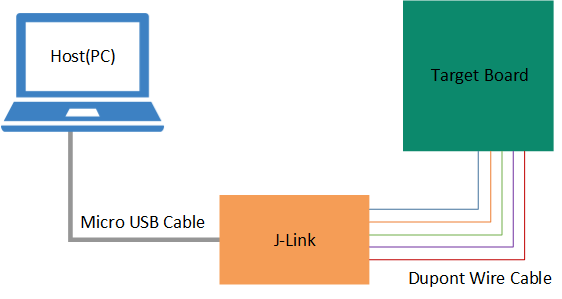
Figure 4 Host-target-board connection in SWD mode The table below lists the mapping relations between J-Link emulator pins and SoC pins.
Table 3 Mapping relations between J-Link emulator pins and SoC pins J-Link Emulator Pin SoC Pin VCC
VCC
GND
GND
SWDIO
GPIO_1
SWCLK
GPIO_0
Note:- For target boards that have been integrated with J-Link emulator chips, you can connect the host to the target board directly through a Micro USB cable.
- For Goodix Starter Kit (SK) Boards, you cannot connect an SK Board to a PC directly via the on-board Micro USB connector (J49) for firmware programming because the integrated ROM upgrade program in the SoC shall be implemented based on a baud rate of 921600, a value which the integrated J-Link emulator chips on the SK Board fails to support.
- UART mode
In UART mode, users need a USB-to-serial converter with one end connecting to the host through a Micro USB cable and the other end connecting to SoC pins of the target board through Dupont wire cables.
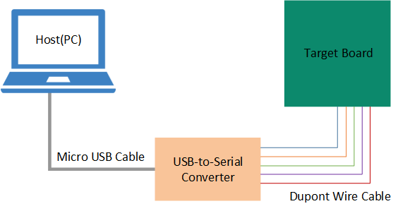
Figure 5 Host-target-board connection in UART mode The table below lists the mapping relations between USB-to-serial converter pins and SoC pins.
Table 4 Mapping relations between USB-to-serial converter pins and SoC pins USB-to-Serial Converter Pin SoC Pin VCC
VCC
GND
GND
TX
GPIO_1
RX
GPIO_0
RTS
CHIP_EN
For target boards that have been integrated with USB-to-serial converter chips, you can connect the host to the target board directly through a Micro USB cable.