Impedance Matching
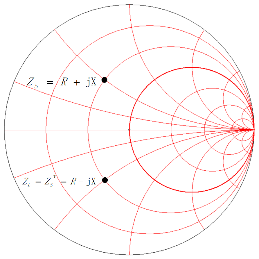
Impedance matching is the process of adjusting the source impedance (assumed as ZS) and load impedance (assumed as ZL) in circuits or systems to maximize power transfer or minimize signal reflection. For complex impedance, if conjugate matching condition is met (ZL = ZS*), then the maximum power transfer can be achieved.
Due to the mismatch between the output impedance of the RF Power Amplifier (PA) and the characteristic impedance of the transmission line (50 Ω), a matching network is required to transform the RF PA output impedance to 50 Ω in order to drive the 50 Ω characteristic impedance transmission line.
In the process of tuning an impedance matching network, pay attention to the following indicators:
- Output power: Needs to meet expectations.
- RX sensitivity: Needs to meet expectations.
- Harmonic suppression performance: It is recommended that the amplitude of each harmonic conduction be no higher than –40 dBm.
- Balance between PA output power and efficiency in different application scenarios