Functional Description
PWM is capable of configurable output frequency dynamically.
PWM block supports three independent outputs: pwma, pwmb and pwmc.
PWM Block has two operation modes: flicker mode and breath mode.
In flicker mode, PWM module outputs successive pulses with certain frequency and duty as configured. In breath mode, the duty of PWM output periodically changes from 0% to 100%, and then 100% to 0% uniformly. The change period is configurable.
under flicker mode, the duty of PWM can be configured in the range of 0% to 100%. The three outputs can be configured independently and they share one output frequency.
Under breath mode, a configurable duration of breath hold state is supported. The breath hold state is set between two adjacent breath processes (i.e. duty change: 0%→100%→0%). In the hold state, the LED driven by PWM stays off.
In flicker mode, edge alignment and center alignment are supported.
Choose edge alignment mode, all open channels are aligned at the beginning of each duty cycle as shown in the figure below.

Choose center alignment mode, all open channels are aligned in the middle of each duty cycle as shown in the figure below.

The configured data can be updated into active registers in three modes: synchronize-all mode (enabled by UPDATE_SYNC_AE), synchronize separate mode (enabled by UPDATE_SYNC_SXX) and asynchronous mode.
Both led-positive-drive mode and led-negative-drive mode are supported and can be configured in DRV_POS_x. In led-positive-drive mode, the LED driven by PWM is lightened when PWM outputs logic 1, and goes off when PWM outputs logic 0. In LED-negative mode, the contrary is the case.
Block Diagram
The PWM block diagram is illustrated in 图 63.

Operation
There are several shadow registers in PWM module. The write operation will first change the shadow registers, and then will update the value of active registers from the shadow registers under certain condition.
Active registers update conditions:
- Under synchronize-all update mode (UPDATE_SYNC_AE = 0x1), all effective registers of flicker mode or breath mode will be updated simultaneously. In flicker mode (BREATH_EN = 0), after writing to PRD, CMPXX and AQCTRL will update from shadow registers simultaneously when the Time Base counter counts to PRD - 1.

图 64 Flicker mode waveform - In breath mode (BREATH_EN = 1), after writing to BRPRD, PRD, BRPRD and HOLD will update from shadow registers simultaneously when the current breath process ends (the moment PWM duty reduces to 0%).

图 65 Breath mode waveform Note:PAUSE cannot be updated in this mode.
- In synchronize-separate update mode (UPDATE_SYNC_SXX = 0x1), CMPXX, AQCTRL and PAUSE will update when the Time Base counter counts to PRD - 1 if the corresponding UPDATE_SYNC_SXX bit is set. BRPRD and HOLD will update when the current breath process ends and the corresponding UPDATE_SYNC_SXX bit is set. PRD will update when Time Base counter counts to PRD - 1 in flicker mode, and will update when current breath ends in breath mode if UPDATE_SYNC_SPRD is set.
- In asynchronous update mode, all registers will update instantly.
- On the rising edge of FLIC_EN or BREATH_EN (FLIC_EN = EN & BREATH_EN, BREATH_EN = EN & BREATH_EN), PRD will update instantly; on the rising edge of FLIC_EN, CMPXX, AQCTRL and PAUSE will update instantly; on the rising edge of BREATH_EN, BRPRD and HOLD will update instantly.
In initial state, UPDATE is configured to set update mode, then PRD, CMPXX, AQCTRL, BRPRD and HOLD registers are configured, and finally, MODE is configured to choose the operation mode and enable the module.
If the configurations need to be changed under sync-all update mode, CMPXX and AQCTRL in flicker mode, or HOLD in breath mode should be written before modifying the values of PRD and BRPRD.
Duty Cycle Calculation
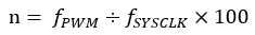
The PWM duty cycle can be configured as an integer from 0 to 100, depending on the following calculation formulas of the duty cycle accuracy "n".
- In PWM_ALIGNED_EDGE mode:
- In PWM_ALIGNED_CENTER mode:
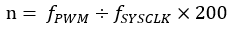
For example, when the clock frequency is 64 MHz and the duty cycle is in the range of 1 to 100, the maximum PWM frequency can only be set to 640 KHz in the PWM_ALIGNED_EDGE mode, and can only be set to 320 KHz in the PWM_ALIGNED_CENTER mode.
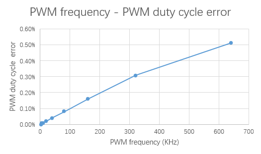
In a system clock with frequency 64 MHz, duty cycle errors at different PWM frequencies are as follows:
| PWM Frequency | PWM Duty Cycle Error |
|---|---|
| 640 KHz | 0.51% |
| 320 KHz | 0.31% |
| 160 KHz | 0.16% |
| 80 KHz | 0.08% |
| 40 KHz | 0.04% |
| 20 KHz | 0.02% |
| 10 KHz | 0.01% |
| 5 KHz | 0.01% |
| 2.5 KHz | <0.01% |
| PWM Frequency | PWM Duty Cycle Error |
|---|---|
| 320 KHz | 0.51% |
| 160 KHz | 0.16% |
| 80 KHz | 0.08% |
| 40 KHz | 0.04% |
| 20 KHz | 0.02% |
| 10 KHz | 0.01% |
| 5 KHz | 0.01% |
| 2.5 KHz | <0.01% |