QSPI
Introduction
The GR5526 SoC supports three instances of Quad Serial Peripheral Interface (QSPI) master, namely QSPI M0, QSPI M1, and QSPI M2, which are used to interface to external slave devices. All the QSPI instances support memory mapped mode that can be used in accessing a storage device such as NOR Flash or PSRAM.
Each QSPI instance can be configured to work with standard SPI/Dual SPI/Quad SPI mode.
Main Features
- Standard/Dual/Quad Motorola SPI support
- Single slave select line to support 1 slave
- Built-in 16-/32-word RX/TX FIFOs for different instances
- Transfer data size up to 32 bits
- Programmable output interface frequency up to 48 MHz
- Supporting four SPI modes for different clock edge and phase configurations
- DMA support
- Access mode support:
- Read and write transfer support in register mode
- Read and write transfer support in memory mapped (XIP) mode
- Supporting free data endian mode in XIP operation (for reads)
- Continuous transfer mode in XIP operation (for reads)
- Data prefetch support in XIP operation (for reads)
- Enhanced (Dual/Quad) SPI features:
- Programmable address, instruction, wait cycles, and data frame size
- Clock stretch feature support
- Programmable receive sample delay support
- Maskable interrupt generation
- Supporting adjusting the CS setup delay time
- Perfect access thoughtput
Functional Description
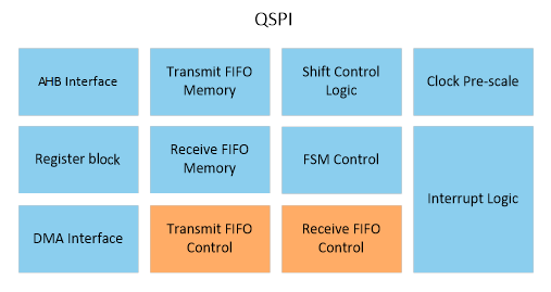
Block Diagram
- AHB interface and DMA controller interface
- Transmit and receive FIFO controllers and an FSM controller
- Register block
- Shift control and interrupt logic
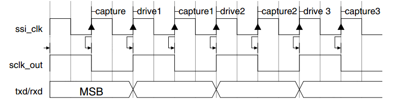
Clock Ratios
The maximum frequency of the bit-rate clock (sclk_out) is one-half the frequency of ssi_clk signal. This is to allow the shift control logic to capture data on one clock edge of sclk_out signal and propagate data on the opposite edge; this is illustrated in the following figure.
The frequency of sclk_out signal can be derived from the following equation.
Where, SCKDV (Baud Rate Register, BAUD[15:0]) is a programmable register holding any even value in the range of 0–65,534. If SCKDV = 0, sclk_out is disabled.
The sclk_out line only toggles when an active transfer is in progress. At all other time, it is held in inactive state, as define by the serial protocol under which it operates.
Motorola Serial Peripheral Interface
For details of the interface, see Motorola Serial Peripheral Interface.
Transmit and Receive FIFO Buffers
The width of both TX and RX FIFO buffers is fixed at 32 bits. Data frames that are less than 32 bits must be right-justified when written into the TX FIFO buffer. The shift control logic automatically right-justifies receive data in the RX FIFO buffer.
Each data entry in the FIFO buffers contains a single data frame. Storing multiple data frames in a single FIFO location is not supported; for example, users may not store two 8-bit data frames in a single FIFO location. If an 8-bit data frame is required, the upper 8-bits of the FIFO entry are ignored or unused when the serial shifter transmits the data.
Transmit FIFO
The TX FIFO is loaded by AHB write commands to the QSPI data register (DATA). Data is popped (removed) from the TX FIFO by the shift control logic into the transmit shift register. The TX FIFO generates a FIFO empty interrupt request (qspi_txe_intrl) when the number of entries in the FIFO is less than or equal to the FIFO threshold value. The threshold value, set through the programmable transmit FIFO threshold level register (TX_FTL[4:0]), determines the level of FIFO entries at which an interrupt is generated. The threshold value allows users to provide early indication to the processor that the TX FIFO is nearly empty. A TX FIFO overflow interrupt (qspi_txo_intr) is generated if users attempt to write data into an already full TX FIFO.
Receive FIFO
Data is popped from the RX FIFO by AHB read commands to the QSPI data register (DATA). The RX FIFO is loaded from the receive shift register by the shift control logic. The RX FIFO generates a FIFO-full interrupt request (qspi_rxf_intr) when the number of entries in the FIFO is greater than or equal to the FIFO threshold value plus 1. The threshold value, set through programmable receive FIFO threshold level register (RX_FTL[4:0]), determines the level of FIFO entries at which an interrupt is generated.
The threshold value allows users to provide early indication to the processor that the RX FIFO is nearly full. A RX FIFO overrun interrupt (qspi_rxo_intr) is generated when the receive shift logic attempts to load data into a completely full RX FIFO. However, this newly received data is lost. A RX FIFO underflow interrupt (qspi_rxu_intr) is generated if users attempt to read from an empty RX FIFO. This alerts the processor that the read data is invalid.
QSPI Interrupts
The QSPI controller supports individual interrupt requests, each of which can be masked.
The QSPI controller interrupts are described as follows:
- TX FIFO empty interrupt (qspi_txe_intr) – Set when the TX FIFO is equal to or below its threshold value and requires service to prevent an under-run. The threshold value, set through a software-programmable register, determines the level of TX FIFO entries at which an interrupt is generated. This interrupt is cleared by hardware when data is written into the TX FIFO buffer, bringing it over the threshold level.
- TX FIFO overflow interrupt (qspi_txo_intr) – Set when an AHB access attempts to write into the TX FIFO after it has been completely filled. When set, data written from the AHB is discarded. This interrupt remains set until users read the TX FIFO error interrupt clear register (TXEICR[0]).
- TX FIFO underflow interrupt (qspi_txu_intr) - Present only when internal DMA mode or SPI bridge mode or XIP write transfer is enabled. The interrupt is set when TX FIFO pop happens from serial FSM and FIFO is empty. This interrupt remains set until users read the TX FIFO error interrupt clear register (TXEICR[0]).
- RX FIFO full interrupt (qspi_rxf_intr) – Set when the RX FIFO is equal to or above its threshold value plus 1 and requires service to prevent an overflow. The threshold value, set through a software-programmable register, determines the level of RX FIFO entries at which an interrupt is generated. This interrupt is cleared by hardware when data is read from the RX FIFO buffer, bringing it below the threshold level.
- RX FIFO overflow interrupt (qspi_rxo_intr) – Set when the receive logic attempts to place data into the RX FIFO after it has been completely filled. When set, newly received data is discarded. This interrupt remains set until users read the RX FIFO overflow interrupt clear register (RXOICR[0]).
- RX FIFO underflow interrupt (qspi_rxu_intr) – Set when an AHB access attempts to read from the RX FIFO when it is empty. When set, zeros are read back from the RX FIFO. This interrupt remains set until users read the RX FIFO underflow interrupt clear register (RXUICR[0]).
Transfer Modes
When transferring data on the serial bus, the SPI controller operates in the modes discussed in this section. The transfer mode (TMOD) is set by writing to bit8 and bit9 of the SPI control register 0 (CTRL0).
The transfer mode setting does not affect the duplex of the serial transfer.
Transmit and Receive
When CTRL0[11:10] = 0x0, both transmit and receive logics are valid. The data transfer occurs as normal according to the selected frame format (serial protocol). Transmit data is popped from the TX FIFO and sent through the TXD line to the target device, which replies with data on the RXD line. The receive data from the target device is moved from the receive shift register into the RX FIFO at the end of each data frame.
Transmit Only
When CTRL0[11:10] = 0x1, the received data is invalid and should not be stored in the RX FIFO. The data transfer occurs as normal, according to the selected frame format (serial protocol). Transmit data is popped from the TX FIFO and sent through the TXD line to the target device, which replies with data on the RXD line. At the end of the data frame, the receive shift register does not load its newly received data into the RX FIFO. The data in the receive shift register is overwritten by the next transfer. Users should mask interrupts originating from the receive logic when this mode is entered.
Receive Only
When CTRL0[11:10] = 0x2, the transmit data is invalid. When QSPI is configured as a slave, the TX FIFO is never popped in Receive Only mode. The TXD output remains at a constant logic level during the transmission. The data transfer occurs as normal according to the selected frame format (serial protocol). The receive data from the target device is moved from the receive shift register into the RX FIFO at the end of each data frame. Users should mask interrupts originating from the transmit logic when this mode is entered.
EEPROM Read
When CTRL0[11:10] = 0x3, the transmit data is used to transmit an opcode and/or an address to the EEPROM device. Typically, this takes three data frames (8-bit opcode followed by 8-bit upper address and 8-bit lower address). During the transmission of the opcode and address, no data is captured by the receive logic (as long as the SPI controller master is transmitting data on its TXD line, data on the RXD line is ignored). The QSPI controller master continues to transmit data until the TX FIFO is empty. Therefore, users should only have enough data frames in the TX FIFO to supply the opcode and address to the EEPROM. If more data frames are in the TX FIFO than needed, read data is lost.
When the TX FIFO becomes empty (all control information has been sent), data on the receive line (RXD) is valid and is stored in the RX FIFO; the TXD output is held at a constant logic level. The serial transfer continues until the number of data frames received by the QSPI controller master matches the value of the NDF (Number of Data Frames) field in the SPI Control register 1 (CTRL1[15:0]) + 1.
DMA
In the register mode (non-XIP mode), QSPI uses a handshake request signal to start the DMA transfer. DMA0 instance provides handshake request signals to QSPI0 and QSPI1 instances, and DMA1 instance provides handshake request signals to QSPI1 and QSPI2 instances, so
- QSPI M0 can use DMA0 to receive and transmit data.
- QSPI M1 can use DMA0/DMA1 to receive and transmit data.
- QSPI M2 can use DMA1 to receive and transmit data.
Meanwhile, Channel0 and Channel1 of DMA have the biggest FIFO depth. It is suggested to assign the Channel0 & Channel1 of DMA to QSPI instances to get the maximum throughput.
Clock Stretching in Enhanced SPI Transfers
While QSPI is transmitting or receiving data from a QSPI slave device, the software may not be able to keep up with the transfer rate due to the bandwidth issues on the slave interface. In such cases, TX FIFO becomes empty or RX FIFO overflows while transmitting and receiving the data.
To avoid data corruption, CPU must discard the current operation and start a new transfer. This process is time consuming and inefficient.
To handle such scenarios, clock stretching support has been added in QSPI.
- For write transactions, whenever TX FIFO becomes empty, QSPI does not de-select the slave. Instead, it masks the clock until the new data is pushed into the TX FIFO. Hence, the transfer is not broken, and CPU intervention is not required. The transfer is resumed after the TX FIFO receives at least one FIFO entry.
- For read transactions, similar to the write transaction, whenever QSPI detects that RX FIFO is full, the clock is masked until the data is read from FIFO. The transfer is resumed when FIFO level goes below the set threshold level in the RX_FTL[4:0] register.
QSPI block provides a programming bit (CLK_STRETCH_EN) in QSPI enhanced control register 0 (SPI_CTRL0[30]) to enable clock stretching feature.
Memory Mapped Mode (XIP Mode)
QSPI module allows directly performing memory read operations from AHB transaction. This is called memory mapped access mode (also called XIP mode), in which QSPI acts as memory mapped interface to an SPI memory.
Memory Mapped Read Model
XIP read operation works under memory mapped mode. Typical devices are NOR Flash and PSRAM with QSPI/DSPI interface.
XIP operations are supported only in Dual or Quad enhanced SPI modes of operation, so bit (SPI_FRF) of the CTRL0[23:22] must not be programmed to 0. When CTRL0[23:22] = 0x1, select Dual SPI frame format. When CTRL0[23:22] = 0x2, select Quad SPI frame format. Typically, an XIP operation consists of an address phase and a data phase. The programming flow to set up an XIP transfer is as follows:
- Set the SPI protocol format value to Motorola format in CTRL0.FRF register.
- Set the SPI frame format value in XIP_CTRL.FRF register.
- Set the address length, wait cycles, and transaction type in XIP_CTRL.ADDR_L register. It should be noted that the maximum address length is 32 bits.
The instruction phase can also be included in XIP transfer by using INST_EN field of the XIP_CTRL register. In this case, the following registers must be set:
- Set length of instruction in the INST_L field of XIP_CTRL[10:9] register.
- Write the instruction opcodes in the XIP_INCR_INST[15:0] and XIP_WRAP_INST[15:0] registers.
After the programming is complete, users can initiate a read transaction through the AHB interface that is transferred to the SPI peripheral using programmed values.
After finishing above setting, users can read the device’s data by accessing the corresponding QSPI’s memory mapped space.
Memory Mapped Write Model
XIP write feature can be used to access PSRAM device supporting QSPI/DSPI interface (it cannot be used to write the NOR Flash device). Each typical write time meets with the PSRAM’s tCEM time.
XIP operations are supported only in enhanced SPI modes of operation (Dual and Quad modes).
QSPI can write into the DSPI/QSPI interface memory without software overhead of writing the instruction and address separately into the transmit buffer. XIP write feature executes the write transactions directly without software intervention.
The programming flow to set up an XIP transfer is as follows:
- Set the SPI frame format value in XIP_WR_CTRL. WR_CTRL_FRF register.
- Set the address length, wait cycles, and transaction type in XIP_WR_CTRL.WR_CTRL_ADDRL. It should be noted that the maximum address length is 32 bits.
- Set length of instruction in the XIP_WR_CTRL.WR_INST_L register.
- Write the instruction opcodes in the XIP_WR_INCR_INST and XIP_WR_WRAP_INST registers.
Memory Mapped Space
After activating the memory mapped mode, users can perform access operations from AHB transaction. The AHB memory space for QSPI instances are allocated as 图 76.

- QSPI0 memory mapped space is from C0000000 to C3FFFFFF; 65,536 KB in total.
- QSPI1 memory mapped space is from C4000000 to C7FFFFFF; 65,536 KB in total.
- QSPI2 memory mapped space is from C8000000 to CBFFFFFF; 65,536 KB in total.
Data Endian Mode for Memory Mapped Read Model
QSPI supports different endian data in XIP Read mode. Users can refer to the following chart to configure the endian mode as needed. The related register is QSPI_MODE_XIP register.
| AHB Address | 0xAC0 00000 | 0xAC00 0001 | 0xAC00 0002 | 0xAC000003 | 0xAC000004 | 0xAC000005 | 0xAC000006 | 0xAC000007 | 0xAC000008 | 0xAC000009 | 0xAC00000A | 0xAC00000B |
|---|---|---|---|---|---|---|---|---|---|---|---|---|
PSRAM Address |
0x000000 |
0x000001 |
0x000002 |
0x000003 |
0x000004 |
0x000005 |
0x000006 |
0x000007 |
0x000008 |
0x000009 |
0x00000A |
0x00000B |
Saved Data |
0x01 |
0x02 |
0x03 |
0x04 |
0x05 |
0x06 |
0x07 |
0x08 |
0x09 |
0x0A |
0x0B |
0x0C |
| Data Type | By Byte | By Short | By Integer | |||||
|---|---|---|---|---|---|---|---|---|
| Access Addr/ Endian Mode |
0xAC000000 |
0xAC000001 |
0xAC000002 |
0xAC000003 |
0xAC000000 |
0xAC000002 |
0xAC000000 |
0xAC000004 |
| Mode 0/3 |
0x01 |
0x02 |
0x03 |
0x04 |
0x0102 |
0x0304 |
0x01020304 |
0x05060708 |
| Mode 1 |
0x01 |
0x02 |
0x03 |
0x04 |
0x0201 |
0x0403 |
0x02010403 |
0x06050807 |
| Mode 2 |
0x01 |
0x02 |
0x03 |
0x04 |
0x0201 |
0x0403 |
0x04030201 |
0x08070605 |
Enhanced Feature
Related Delay Between CS and SCK
Tcsu (CS Setup Delay Time) is an important parameter to access QSPI device. If Tcsu is not enough, the access may fail.
Tch (CS Release Delay Time) is symmetric to Tcsu.
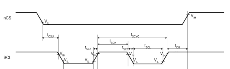
If necessary, users can set the two parameters wider to fit with devices’ requirement. The related registers are QSPI_CS_SETUP_DLY and QSPI_CS_RELEASE_DLY.
Registers
CTRL0
- Name: QSPI Control Register 0
- Description: This register controls the serial data transfer. It is impossible to write to this register when the QSPI is enabled.
- Base Address: QSPI0: 0x40023000; QSPI1: 0x40022000; QSPI2: 0x40021000
- Offset: 0x00
- Reset Value: 0x01070000
| Bits | Field Name | RW | Reset | Description |
|---|---|---|---|---|
31:24 |
RSVD |
R |
Reserved bits |
|
23:22 |
SPI_FRF |
RW |
0x0 |
QSPI frame format: Selects data frame format for transmitting/receiving the data bits. Value:
|
21:15 |
RSVD |
R |
Reserved bits |
|
14 |
SSTEN |
RW |
0x0 |
Slave select toggle enable. When operating in SPI mode with clock phase (SCPH) set to 0, this register controls the behavior of the slave select line (CS) between data frames. If this register field is set to 1, the CS line will toggle between consecutive data frames, with the serial clock (SCLK) being held to its default value while CS is high; if this register field is set to 0, the CS will stay low and SCLK will run continuously for the duration of the transfer. Note: When the SPI is configured as a slave, this register serves no purpose. |
13 |
SRL |
RW |
0x0 |
Shift register loop. Used for testing purposes only. When internally active, connects the transmit shift register output to the receive shift register input. Value:
|
12 |
SLVOE |
RW |
0x0 |
Slave output enable. Value:
|
11:10 |
TMOD |
RW |
0x0 |
Transfer mode. This transfer mode is only valid when the SPI is configured as master device. Value:
|
9 |
SCPOL |
RW |
0x0 |
Serial clock polarity. Valid when the frame format (FRF) is set to Motorola SPI. Used to select the polarity of the inactive serial clock, which is held inactive when the SPI master is not actively transferring data on the serial bus. Value:
|
8 |
SCPHA |
RW |
0x0 |
Serial clock phase. Valid when the frame format (FRF) is set to Motorola SPI. The serial clock phase selects the relationship of the serial clock with the slave select signal. When SCPH = 0, data is captured on the first edge of the serial clock. When SCPH = 1, the serial clock starts toggling one cycle after the slave select line is activated, and data is captured on the second edge of the serial clock. Value:
|
7:6 |
FRF |
RW |
0x0 |
Frame format. Selects which serial protocol transfers the data. Value:
|
5 |
RSVD |
R |
Reserved bits |
|
4:0 |
DFS |
RW |
0x7 |
Data frame size in 32-bit transfer size mode. Used to select the data frame size in 32-bit transfer mode. When the data frame size is programmed to be less than 32 bits, the receive data is automatically right-justified by the receive logic, with the upper bits of the receive FIFO zero-padded. Users are responsible for making sure that transmit data is right-justified before writing into the transmit FIFO. The transmit logic ignores the upper unused bits when transmitting the data. Value:
|
CTRL1
- Name: QSPI Control Register 1
- Description: Control register 1 controls the end of serial transfers in receive only mode. It is impossible to write to this register when the QSPI is enabled.
- Base Address: QSPI0: 0x40023000; QSPI1: 0x40022000; QSPI2: 0x40021000
- Offset: 0x04
- Reset Value: 0x00000000
| Bits | Field Name | RW | Reset | Description |
|---|---|---|---|---|
31:16 |
RSVD |
R |
Reserved bits |
|
15:0 |
NDF |
RW |
0x0 |
Number of data frames. When CTRL0[11:10] = 0x2 or CTRL0[11:10] = 0x3, this register field sets the number of data frames to be continuously received by the QSPI. The QSPI continues to receive serial data until the number of data frames received is equal to this register value plus 1, which enables users to receive up to 64 KB of data in a continuous transfer. |
QSPI_EN
- Name: QSPI Enable Register
- Description: This register enables and disables the QSPI.
- Base Address: QSPI0: 0x40023000; QSPI1: 0x40022000; QSPI2: 0x40021000
- Offset: 0x08
- Reset Value: 0x00000000
| Bits | Field Name | RW | Reset | Description |
|---|---|---|---|---|
31:1 |
RSVD |
R |
Reserved bits |
|
0 |
SSI_EN |
RW |
0x0 |
QSPI enable. Enables and disables all QSPI operations. When disabled, all serial transfers are halted immediately. Transmit and receive FIFO buffers are cleared when the device is disabled. Value:
|
MWC
- Name: Microwire Control Register
- Description: This register controls the direction of the data word for the half-duplex Microwire serial protocol. It is impossible to write to this register when the QSPI is enabled.
- Base Address: QSPI0: 0x40023000; QSPI1: 0x40022000; QSPI2: 0x40021000
- Offset: 0x0C
- Reset Value: 0x00000000
| Bits | Field Name | RW | Reset | Description |
|---|---|---|---|---|
31:3 |
RSVD |
R |
Reserved bits |
|
2 |
MHS |
RW |
0x0 |
Microwire handshaking. Used to enable and disable the busy/ready handshaking interface for the Microwire protocol. When this bit is enabled, the QSPI checks for a ready status from the target slave, after the transfer of the last data/control bit, before clearing the BUSY status in the STAT register. Value:
|
1 |
MDD |
RW |
0x0 |
Microwire control. Defines the direction of the data word when the Microwire serial protocol is used. Value:
|
0 |
MWMOD |
RW |
0x0 |
Microwire transfer mode. Defines whether the Microwire transfer is sequential or non-sequential. When sequential mode is used, only one control word is needed to transmit or receive a block of data words. When non-sequential mode is used, there must be a control word for each data word that is transmitted or received. Value:
|
SE
- Name: Slave Enable Register
- Description: The register enables the individual slave select output lines from the QSPI master.
- Base Address: QSPI0: 0x40023000; QSPI1: 0x40022000; QSPI2: 0x40021000
- Offset: 0x10
- Reset Value: 0x00000000
| Bits | Field Name | RW | Reset | Description |
|---|---|---|---|---|
31:1 |
RSVD |
R |
Reserved bits |
|
0 |
SLAVE0 |
RW |
0x0 |
Slave select enable. Each bit in this register corresponds to a slave select line (CSn) from the QSPI master. Value:
Note: When the QSPI is configured as a slave, this register serves no purpose. |
BAUD
- Name: Baud Rate Register
- Description: The register derives the frequency of the serial clock that regulates the data transfer. It is impossible to write to this register when the QSPI is enabled.
- Base Address: QSPI0: 0x40023000; QSPI1: 0x40022000; QSPI2: 0x40021000
- Offset: 0x14
- Reset Value: 0x00000000
| Bits | Field Name | RW | Reset | Description |
|---|---|---|---|---|
31:16 |
RSVD |
R |
Reserved bits |
|
15:0 |
SCLKDIV |
RW |
0x0 |
QSPI clock divider. The LSB for this field is always set to 0 and is unaffected by a write operation, which ensures an even value is held in this register. If the value is 0, the serial output clock (sclk_out) is disabled. The frequency of the sclk_out is derived from the following equation: Fsclk_out = Fssi_clk/SCKDV |
TX_FTL
- Name: Transmit FIFO Threshold Level Register
- Description: This register controls the threshold value for the transmit FIFO memory.
- Base Address: QSPI0: 0x40023000; QSPI1: 0x40022000; QSPI2: 0x40021000
- Offset: 0x18
- Reset Value: 0x00000000
| Bits | Field Name | RW | Reset | Description |
|---|---|---|---|---|
31:5 |
RSVD |
R |
Reserved bits |
|
20:16 |
TXFTHR |
RW |
0x0 |
Transfer start FIFO level. Used to control the level of entries in transmit FIFO above which transfer will start on serial line. This register can be used to ensure that sufficient data is present in transmit FIFO before starting a write operation on serial line. |
15:5 |
RSVD |
R |
Reserved bits |
|
4:0 |
TFT |
RW |
0x0 |
Transmit FIFO threshold. Controls the level of entries at (or below) which the transmit FIFO controller triggers an interrupt. The FIFO depth is configurable in 16/32 words; this register is sized to the number of address bits needed to access the FIFO. If users attempt to set this value greater than or equal to the depth of the FIFO, this field is not written and retains its current value. When the number of transmit FIFO entries is less than or equal to this value, the transmit FIFO empty interrupt is triggered. |
RX_FTL
- Name: Receive FIFO Threshold Level Register
- Description: This register controls the threshold value for the receive FIFO memory.
- Base Address: QSPI0: 0x40023000; QSPI1: 0x40022000; QSPI2: 0x40021000
- Offset: 0x1C
- Reset Value: 0x00000000
| Bits | Field Name | RW | Reset | Description |
|---|---|---|---|---|
31:5 |
RSVD |
R |
Reserved bits |
|
4:0 |
RFT |
RW |
0x0 |
Receive FIFO threshold. Controls the level of entries at (or above) which the receive FIFO controller triggers an interrupt. The FIFO depth is configurable in 16/32 words. This register is sized to the number of address bits needed to access the FIFO. If users attempt to set this value greater than the depth of the FIFO, this field is not written and retains its current value. When the number of receive FIFO entries is greater than or equal to this value + 1, the receive FIFO full interrupt is triggered. |
TX_FL
- Name: Transmit FIFO Level Register
- Description: This register contains the number of valid data entries in the transmit FIFO memory.
- Base Address: QSPI0: 0x40023000; QSPI1: 0x40022000; QSPI2: 0x40021000
- Offset: 0x20
- Reset Value: 0x00000000
| Bits | Field Name | RW | Reset | Description |
|---|---|---|---|---|
31:6 |
RSVD |
R |
Reserved bits |
|
5:0 |
TX_FL |
R |
0x0 |
Transmit FIFO level. Contains the number of valid data entries in the transmit FIFO. |
RX_FL
- Name: Receive FIFO Level Register
- Description: This register contains the number of valid data entries in the receive FIFO memory. This register can be ready at any time.
- Base Address: QSPI0: 0x40023000; QSPI1: 0x40022000; QSPI2: 0x40021000
- Offset: 0x24
- Reset Value: 0x00000000
| Bits | Field Name | RW | Reset | Description |
|---|---|---|---|---|
31:6 |
RSVD |
R |
Reserved bits |
|
5:0 |
RX_FL |
R |
0x0 |
Receive FIFO level. Contains the number of valid data entries in the receive FIFO. |
STAT
- Name: Status Register
- Description: This is a read-only register used to indicate the current transfer status, FIFO status, and any transmission/reception errors that may have occurred. The status register may be read at any time.
- Base Address: QSPI0: 0x40023000; QSPI1: 0x40022000; QSPI2: 0x40021000
- Offset: 0x28
- Reset Value: 0x00000006
| Bits | Field Name | RW | Reset | Description |
|---|---|---|---|---|
31:7 |
RSVD |
R |
Reserved bits |
|
6 |
DCOL |
R |
0x0 |
Data collision error. This bit will be set if MISO input is asserted by other master, when the QSPI master is in the middle of the transfer. This informs the processor that the last data transfer was halted before completion. This bit is cleared when read. |
5 |
TXE |
R |
0x0 |
Transmission Error. Set if the transmit FIFO is empty when a transfer is started. Data from the previous transmission is resent on the TXD line. This bit is cleared when read. Value:
|
4 |
RFF |
R |
0x0 |
Receive FIFO full. When the receive FIFO is completely full, this bit is set. When the receive FIFO contains one or more empty locations, this bit is cleared. Value:
|
3 |
RFNE |
R |
0x0 |
Receive FIFO not empty. Set when the receive FIFO contains one or more entries and is cleared when the receive FIFO is empty. This bit can be polled by software to completely empty the receive FIFO. Value:
|
2 |
TFE |
R |
0x1 |
Transmit FIFO empty. When the transmit FIFO is completely empty, this bit is set. When the transmit FIFO contains one or more valid entries, this bit is cleared. This bit field does not request an interrupt. Value:
|
1 |
TFNF |
R |
0x1 |
Transmit FIFO not full. Set when the transmit FIFO contains one or more empty locations, and is cleared when the FIFO is full. Value:
|
0 |
BUSY |
R |
0x0 |
QSPI busy flag. This bit being set indicates that a serial transfer is in progress; this bit being cleared indicates that the QSPI is idle or disabled. Value:
|
INTMASK
- Name: Interrupt Mask Register
- Description: This read/write reigster masks or enables all interrupts generated by the QSPI. When the QSPI is configured as a slave device, the MSTIM bit field is not present. This changes the reset value from 0x3F for serial-master configurations to 0x1F for serial-slave configurations.
- Base Address: QSPI0: 0x40023000; QSPI1: 0x40022000; QSPI2: 0x40021000
- Offset: 0x2C
- Reset Value: master ? 0x0000003F: 0x0000001F
| Bits | Field Name | RW | Reset | Description |
|---|---|---|---|---|
31:6 |
RSVD |
R |
Reserved bits |
|
5 |
MSTIM |
RW |
0x1 |
Multi-master contention interrupt mask. Value:
|
4 |
RXFIM |
RW |
0x1 |
Receive FIFO full interrupt mask Value:
|
3 |
RXOIM |
RW |
0x1 |
Receive FIFO overflow interrupt mask Value:
|
2 |
RXUIM |
RW |
0x1 |
Receive FIFO underflow interrupt mask Value:
|
1 |
TXOIM |
RW |
0x1 |
Transmit FIFO overflow interrupt mask Value:
|
0 |
TXEIM |
RW |
0x1 |
Transmit FIFO empty interrupt mask Value:
|
INTSTAT
- Name: Interrupt Status Register
- Description: This register reports the status of the QSPI interrupts after they have been enabled.
- Base Address: QSPI0: 0x40023000; QSPI1: 0x40022000; QSPI2: 0x40021000
- Offset: 0x30
- Reset Value: 0x00000000
| Bits | Field Name | RW | Reset | Description |
|---|---|---|---|---|
31:6 |
RSVD |
R |
Reserved bits |
|
5 |
MSTIS |
R |
0x0 |
Multi-master contention interrupt status Value:
|
4 |
RXFIS |
R |
0x0 |
Receive FIFO full interrupt status Value:
|
3 |
RXOIS |
R |
0x0 |
Receive FIFO overflow interrupt status Value:
|
2 |
RXUIS |
R |
0x0 |
Receive FIFO underflow interrupt status Value:
|
1 |
TXOIS |
R |
0x0 |
Transmit FIFO overflow interrupt status Value:
|
0 |
TXEIS |
R |
0x0 |
Transmit FIFO empty interrupt status Value:
|
RAW_INTSTAT
- Name: Raw Interrupt Status Register
- Description: This read-only register reports the status of the QSPI interrupts prior to being enabled.
- Base Address: QSPI0: 0x40023000; QSPI1: 0x40022000; QSPI2: 0x40021000
- Offset: 0x34
- Reset Value: 0x00000000
| Bits | Field Name | RW | Reset | Description |
|---|---|---|---|---|
31:6 |
RSVD |
R |
Reserved bits |
|
5 |
MSTIR |
R |
0x0 |
Multi-master contention raw interrupt status Value:
|
4 |
RXFIR |
R |
0x0 |
Receive FIFO full raw interrupt status Value:
|
3 |
RXOIR |
R |
0x0 |
Receive FIFO overflow raw interrupt status Value:
|
2 |
RXUIR |
R |
0x0 |
Receive FIFO underflow raw interrupt status Value:
|
1 |
TXOIR |
R |
0x0 |
Transmit FIFO overflow raw interrupt status Value:
|
0 |
TXEIR |
R |
0x0 |
Transmit FIFO empty raw interrupt status Value:
|
TXEIC
- Name: Transmit FIFO Error Interrupt Clear Register
- Description: This register is used to clear the transmit FIFO error interrupt.
- Base Address: QSPI0: 0x40023000; QSPI1: 0x40022000; QSPI2: 0x40021000
- Offset: 0x38
- Reset Value: 0x00000000
| Bits | Field Name | RW | Reset | Description |
|---|---|---|---|---|
31:1 |
RSVD |
R |
Reserved bits |
|
0 |
TXEIC |
R |
0x0 |
Clear transmit FIFO overflow/underflow interrupt. This register reflects the status of the interrupt. A read from this register clears the txo_intr interrupt; writing has no effect. |
RXOIC
- Name: Receive FIFO Overflow Interrupt Clear Register
- Description: This register is used to clear the receive FIFO overflow interrupt.
- Base Address: QSPI0: 0x40023000; QSPI1: 0x40022000; QSPI2: 0x40021000
- Offset: 0x3C
- Reset Value: 0x00000000
| Bits | Field Name | RW | Reset | Description |
|---|---|---|---|---|
31:1 |
RSVD |
R |
Reserved bits |
|
0 |
RXOIC |
R |
0x0 |
Clear receive FIFO overflow interrupt. This register reflects the status of the interrupt. A read from this register clears the rxo_intr interrupt; writing has no effect. |
RXUIC
- Name: Receive FIFO Underflow Interrupt Clear Register
- Description: This register is used to clear the receive FIFO underflow interrupt.
- Base Address: QSPI0: 0x40023000; QSPI1: 0x40022000; QSPI2: 0x40021000
- Offset: 0x40
- Reset Value: 0x00000000
| Bits | Field Name | RW | Reset | Description |
|---|---|---|---|---|
31:1 |
RSVD |
R |
Reserved bits |
|
0 |
RXUIC |
R |
Clear receive FIFO underflow interrupt. This register reflects the status of the interrupt. A read from this register clears the rxu_intr interrupt; writing has no effect. |
MSTIC
- Name: Multi-Master Interrupt Clear Register
- Description: This register is used to clear the multi-master interrupt.
- Base Address: QSPI0: 0x40023000; QSPI1: 0x40022000; QSPI2: 0x40021000
- Offset: 0x44
- Reset Value: 0x00000000
| Bits | Field Name | RW | Reset | Description |
|---|---|---|---|---|
31:1 |
RSVD |
R |
Reserved bits |
|
0 |
MSTIC |
R |
Clear multi-master contention interrupt. This register reflects the status of the interrupt. A read from this register clears the mst_intr interrupt; writing has no effect. |
INTCLR
- Name: Interrupt Clear Register
- Description: This register is used to clear interrupts.
- Base Address: QSPI0: 0x40023000; QSPI1: 0x40022000; QSPI2: 0x40021000
- Offset: 0x48
- Reset Value: 0x00000000
| Bits | Field Name | RW | Reset | Description |
|---|---|---|---|---|
31:1 |
RSVD |
R |
Reserved bits |
|
0 |
INTCLR |
R |
Clear interrupts. This register is set if any of the interrupts below are active. A read clears the txo_intr, rxu_intr, rxo_intr, and the mst_intr interrupts. Writing to this register has no effect. |
DMAC
- Name: DMA Control Register
- Description: The register is used to enable the DMA Controller interface operation.
- Base Address: QSPI0: 0x40023000; QSPI1: 0x40022000; QSPI2: 0x40021000
- Offset: 0x4C
- Reset Value: 0x00000000
| Bits | Field Name | RW | Reset | Description |
|---|---|---|---|---|
31:2 |
RSVD |
R |
Reserved bits |
|
1 |
TDMAE |
RW |
Transmit DMA enable. This bit enables/disables the TX FIFO DMA channel. Value:
|
|
0 |
RDMAE |
RW |
Receive DMA enable. This bit enables/disables the receive FIFO DMA channel. Value:
|
DMA_TDL
- Name: DMA Transmit Data Level Register
- Description: This register controls the threshold value for the TX FIFO memory.
- Base Address: QSPI0: 0x40023000; QSPI1: 0x40022000; QSPI2: 0x40021000
- Offset: 0x50
- Reset Value: 0x00000000
| Bits | Field Name | RW | Reset | Description |
|---|---|---|---|---|
31:5 |
RSVD |
R |
Reserved bits |
|
4:0 |
DMA_TDL |
RW |
Transmit data level. This bit field controls the level at which a DMA request is made by the transmit logic. It is equal to the watermark level; that is, the dma_tx_req signal is generated when the number of valid data entries in the TX FIFO is equal to or below this field value, and TDMAE = 1. |
DMA_RDL
- Name: DMA Receive Data Level Register
- Description: This register controls the threshold value for the receive FIFO memory.
- Base Address: QSPI0: 0x40023000; QSPI1: 0x40022000; QSPI2: 0x40021000
- Offset: 0x54
- Reset Value: 0x00000000
| Bits | Field Name | RW | Reset | Description |
|---|---|---|---|---|
31:5 |
RSVD |
R |
Reserved bits |
|
4:0 |
DMA_RDL |
RW |
Receive data level. This bit field controls the level at which a DMA request is made by the receive logic. The watermark level = DMA_RDL+1; that is, dma_rx_req is generated when the number of valid data entries in the receive FIFO is equal to or above this field value + 1, and RDMAE=1. |
DATA
- Name: Data Register
- Description: The QSPI data register is a 32-bit read/write buffer for the TX/RX FIFOs. When the register is read, data in the RX FIFO buffer is accessed. When it is written to, data is moved into the TX FIFO buffer; a write can occur only when SSI_EN[0] = 1. FIFOs are reset when SSI_EN[0] = 0.
- Base Address: QSPI0: 0x40023000; QSPI1: 0x40022000; QSPI2: 0x40021000
- Offset: 0x60
- Reset Value: 0x00000000
| Bits | Field Name | RW | Reset | Description |
|---|---|---|---|---|
31:0 |
DATA |
RW |
Data register. When writing to this register, users must right-justify the data. Read data is automatically right-justified. |
RX_SMP_DLY
- Name: Receive Sample Delay Register
- Description: This register controls the number of SCLK cycles that are delayed (from the default sample time) before the actual sample of the RXD input occurs. It is impossible to write to this register when the QSPI is enabled.
- Base Address: QSPI0: 0x40023000; QSPI1: 0x40022000; QSPI2: 0x40021000
- Offset: 0xF0
- Reset Value: 0x00000000
| Bits | Field Name | RW | Reset | Description |
|---|---|---|---|---|
3:0 |
RX_SAMPLEDLY |
RW |
Receive sample delay |
SPI_CTRL0
- Name: QSPI Enhanced Control Register 0
- Description: This register is used to control the serial data transfer in enhanced SPI mode of operation. The register is relevant only when CTRL0.SPI_FRF is set to either 01 or 10 or 11. It is impossible to write to this register when the QSPI is enabled.
- Base Address: QSPI0: 0x40023000; QSPI1: 0x40022000; QSPI2: 0x40021000
- Offset: 0xF4
- Reset Value: 0x00000000
| Bits | Field Name | RW | Reset | Description |
|---|---|---|---|---|
31 |
RSVD |
R |
Reserved bits |
|
30 |
CLK_STRETCH_EN |
RW |
0x0 |
Enables clock stretching capability in QSPI transfers.
|
29:16 |
RSVD |
R |
Reserved bits |
|
15:11 |
WAITCYCLES |
RW |
0x0 |
Wait cycles in Dual/Quad mode between control frames transmit and data reception. Specified as number of QSPI clock cycles. |
10 |
RSVD |
R |
Reserved bit |
|
9:8 |
INSTL |
RW |
0x0 |
Dual/Quad mode instruction length in bits. Value:
|
7:6 |
RSVD |
R |
Reserved bits |
|
5:2 |
ADDRL |
RW |
0x0 |
These bits define the length of address to be transmitted. Only after these bits are programmed into the FIFO, the transfer can begin. Value:
|
1:0 |
TRANSTYPE |
RW |
0x0 |
Address and instruction transfer format. Selects whether QSPI will transmit instruction/address either in standard SPI mode or the SPI mode selected in CTRL0.SPI_FRF field. Value:
|
XIP_MODE_BITS
- Name: XIP Mode Bits Register
- Description: This register carries the mode bits which are sent in the XIP mode of operation after address phase. This is an 8-bit register and can only be written when SE register is set to 0.
- Base Address: QSPI0: 0x40023000; QSPI1: 0x40022000; QSPI2: 0x40021000
- Offset: 0xFC
- Reset Value: 0x00000000
| Bits | Field Name | RW | Reset | Description |
|---|---|---|---|---|
15:0 |
MODE_BITS |
RW |
XIP mode bits to be sent after address phase of XIP transfer |
XIP_INCR_INST
- Name: XIP INCR Transfer Opcode Register
- Description: This register is used to store the instruction op-code to be used in INCR transactions when the same is requested on AHB interface. It is impossible to write to this register when the QSPI is enabled.
- Base Address: QSPI0: 0x40023000; QSPI1: 0x40022000; QSPI2: 0x40021000
- Offset: 0x100
- Reset Value: 0x00000000
| Bits | Field Name | RW | Reset | Description |
|---|---|---|---|---|
15:0 |
XIP_INCR_INST |
RW |
0x00 |
XIP INCR transfer opcode. When XIP_CTRL.INST_EN bit is set to 1, QSPI sends instruction for all XIP transfers, this register field stores the instruction op-code to be sent when an INCR type transfer is requested on AHB bus. The number of bits to be sent in instruction phase is determined by XIP_CTRL.INST_L field. |
XIP_WRAP_INST
- Name: XIP WRAP Transfer Opcode Register
- Description: This register is used to store the instruction op-code to be used in WRAP transactions when the same is requested on AHB interface. It is impossible to write to this register when the QSPI is enabled.
- Base Address: QSPI0: 0x40023000; QSPI1: 0x40022000; QSPI2: 0x40021000
- Offset: 0x104
- Reset Value: 0x00000000
| Bits | Field Name | RW | Reset | Description |
|---|---|---|---|---|
15:0 |
XIP_WRAP_INST |
RW |
0x00 |
XIP WRAP transfer opcode. When XIP_CTRL.INST_EN bit is set to 1, QSPI sends instruction for all XIP transfers, this register field stores the instruction op-code to be sent when a WRAP type transfer is requested on AHB bus. The number of bits to be sent in instruction phase is determined by XIP_CTRL.INST_L field. |
XIP_CTRL
- Name: XIP Control Register
- Description: This register is used to store the control information for the XIP transfer. It is impossible to write to this register when the QSPI is enabled.
- Base Address: QSPI0: 0x40023000; QSPI1: 0x40022000; QSPI2: 0x40021000
- Offset: 0x108
- Reset Value: 0x00000000
| Bits | Field Name | RW | Reset | Description |
|---|---|---|---|---|
31:30 |
RSVD |
R |
Reserved bits |
|
29 |
XIP_PREFETCH_EN |
RW |
0x0 |
Enables XIP pre-fetch functionality in QSPI. Once the functionality is enabled, QSPI will pre-fetch data frames from next contiguous location, to reduce the latency for the upcoming contiguous transfer. If the next XIP request is not contiguous, then pre-fetched bits will be discarded. |
28 |
RSVD |
R |
Reserved bit |
|
27:26 |
XIP_MBL |
RW |
0x0 |
XIP Mode bits length. Sets the length of mode bits in XIP mode of operation. These bits are valid only when XIP_CTRL.MD_BITS_EN is set to 1. Value:
|
25:24 |
RSVD |
R |
Reserved bits |
|
23 |
CONT_XFER_EN |
RW |
0x0 |
Enable continuous transfer in XIP mode. If this bit is set to 1, then continuous transfer mode in XIP will be enabled, in this mode QSPI will keep slave selected until a non-XIP transfer is detected on the AHB interface. |
22 |
INST_EN |
RW |
0x0 |
XIP instruction enable bit. If this bit is set to 1, then XIP transfers will also have instruction phase. The instruction op-codes will be chosen from XIP_INCR_INST or XIP_WRAP_INST register based on AHB transfer type. |
21:19 |
RSVD |
R |
Reserved bits |
|
18 |
DFS_HC |
RW |
0x0 |
Fix DFS for XIP transfers. If this bit is set to 1, then data frame size for XIP transfers will be fixed to the programmed value in CTRL0.DFS. The number of data frames to fetch will be determined by HSIZE and HBURST signals. If this bit is set to 0 then data frame size and number of data frames to fetch will be determined by HSIZE and HBURST signals. |
17:13 |
WAIT_CYCLES |
RW |
0x0 |
Wait cycles in Dual/Quad mode between control frames transmit and data reception. Specified as number of QSPI clock cycles. |
12 |
MD_BITS_EN |
RW |
0x0 |
Mode bits enable in XIP mode. If this bit is set to 1, then in XIP mode of operation, QSPI will insert mode bits after the address phase. These bits are set in XIP_MODE_BITS register. The length of mode bits is always set to 8 bits. |
11 |
RSVD |
R |
Reserved bit |
|
10:9 |
INST_L |
RW |
0x0 |
Dual/Quad mode instruction length in bits. Value:
|
8 |
RSVD |
R |
Reserved bit |
|
7:4 |
ADDR_L |
RW |
0x0 |
These bits define the length of address to be transmitted. Only after these bits are programmed into the FIFO, the transfer can begin. Value:
|
3:2 |
TRANS_TYPE |
RW |
0x0 |
Address and instruction transfer format. Selects whether QSPI will transmit instruction/address either in standard SPI mode or the SPI mode selected in CTRL0.SPI_FRF field. Value:
|
1:0 |
FRF |
RW |
0x0 |
QSPI frame format. Selects data frame format for transmitting/receiving the data. Value:
|
XIP_SER
- Name: XIP Slave Enable Register
- Description: The register enables the individual slave select output lines from the QSPI master for XIP mode of operation. Users cannot write to this register when QSPI is busy or when QSPI is enabled.
- Base Address: QSPI0: 0x40023000; QSPI1: 0x40022000; QSPI2: 0x40021000
- Offset: 0x10C
- Reset Value: 0x00000000
| Bits | Field Name | RW | Reset | Description |
|---|---|---|---|---|
31:1 |
RSVD |
R |
Reserved bits |
|
0 |
SLAVE0 |
RW |
0x0 |
Slave select enable flag |
XIP_CNT_TIME_OUT
- Name: XIP Time Out Register for Continuous Transfers
- Description: XIP count down register for continuous mode. The counter is used to de-select the slave during continuous transfer mode. It is impossible to write to this register when the QSPI is enabled.
- Base Address: QSPI0: 0x40023000; QSPI1: 0x40022000; QSPI2: 0x40021000
- Offset: 0x114
- Reset Value: 0x00000000
| Bits | Field Name | RW | Reset | Description |
|---|---|---|---|---|
31:8 |
RSVD |
R |
Reserved bits |
|
7:0 |
XTOC |
RW |
0 |
XIP time out value in terms of HCLK. Once slave is selected in continuous XIP mode, this counter will be used to de-select the slave if there is no request for the time specified in the counter. |
XIP_WR_INCR_INST
- Name: XIP Write INCR Transfer Opcode Register
- Description: This register is used to store the instruction op-code to be used in INCR transactions for XIP Write when the same is requested on AHB interface. It is impossible to write to this register when the QSPI is enabled.
- Base Address: QSPI0: 0x40023000; QSPI1: 0x40022000; QSPI2: 0x40021000
- Offset: 0x140
- Reset Value: 0x00000000
| Bits | Field Name | RW | Reset | Description |
|---|---|---|---|---|
15:0 |
XIP_INCR_INST |
RW |
0x00 |
XIP Write INCR transfer opcode. When XIP_WR_CTRL.INST_L is not equal to 0, QSPI sends instruction for all XIP write transfers, this register field stores the instruction op-code to be sent when an INCR type XIP Write transfer is requested on AHB bus. The number of bits to be sent in instruction phase is determined by XIP_WR_CTRL.INST_L field. |
XIP_WR_WRAP_INST
- Name: XIP Write WRAP Transfer Opcode Register
- Description: This register is used to store the instruction op-code to be used in WRAP transactions for XIP Write when the same is requested on AHB interface. It is impossible to write to this register when the QSPI is enabled.
- Base Address: QSPI0: 0x40023000; QSPI1: 0x40022000; QSPI2: 0x40021000
- Offset: 0x144
- Reset Value: 0x00000000
| Bits | Field Name | RW | Reset | Description |
|---|---|---|---|---|
15:0 |
XIP_WRAP_INST |
RW |
0x00 |
XIP Write WRAP transfer opcode. When XIP_WR_CTRL.INST_L is not equal to 0, QSPI sends instruction for all XIP write transfers, this register field stores the instruction op-code to be sent when a WRAP type XIP Write transfer is requested on AHB bus. The number of bits to be sent in instruction phase is determined by XIP_WR_CTRL.INST_L field. |
XIP_WR_CTRL
- Name: XIP Write Control Register
- Description: This register is used to store the control information that will be used for XIP write transfer in the xip mode. It is impossible to write to this register when the QSPI is enabled.
- Base Address: QSPI0: 0x40023000; QSPI1: 0x40022000; QSPI2: 0x40021000
- Offset: 0x148
- Reset Value: 0x00000000
| Bits | Field Name | RW | Reset | Description |
|---|---|---|---|---|
31:21 |
RSVD |
R |
Reserved bits |
|
20:16 |
WR_CTRL_WAITCYCLES |
RW |
0x0 |
Wait cycles in Dual/Quad mode between control frames transmit and data reception. Specified as number of QSPI clock cycles. |
15:10 |
RSVD |
R |
Reserved bits |
|
9:8 |
WR_CTRL_INSTL |
RW |
0x0 |
Dual/Quad mode instruction length in bits. Value:
|
7:4 |
WR_CTRL_ADDRL |
RW |
0x0 |
This bit defines Length of Address to be transmitted. Only after these bits are programmed into the FIFO, the transfer can begin. Value:
|
3:2 |
WR_CTRL_TRANSTYPE |
RW |
0x0 |
Address and instruction transfer format. Selects whether QSPI will transmit instruction/address either in Standard SPI mode or the SPI mode selected in CTRL0.SPI_FRF field. Value:
|
1:0 |
WR_CTRL_FRF |
RW |
0x0 |
QSPI frame format. Selects data frame format for Transmitting/Receiving the data. Value:
|
QSPI_MODE_XIP
- Name: XIP Endian Mode Configure Register
- Description: This register is used to configure endian mode under XIP read access.
- Base Address: 0xA000E000
- Offset: 0x180
- Reset Value: 0x00000000
| Bits | Field Name | RW | Reset | Description |
|---|---|---|---|---|
31 |
M2_DYNAMIC_LE_EN |
RW |
0x0 |
Configure QSPI2 Dynamic Endian Mode. Value:
|
30 |
M1_DYNAMIC_LE_EN |
RW |
0x0 |
Configure QSPI1 Dynamic Endian Mode. Value:
|
29 |
M0_DYNAMIC_LE_EN |
RW |
0x0 |
Configure QSPI0 Dynamic Endian Mode. Value:
|
28:12 |
RSVD |
RW |
0x0 |
Reserved bits |
11:10 |
M2_STATIC_ENDIAN_MODE |
RW |
0x0 |
Configure QSPI2’s static endian mode for XIP read. Value:
|
9:8 |
M2_XIP_EN |
RW |
0x0 |
Control the QSPI2’s XIP mode to turn to active or inactive. Value:
|
7:6 |
M1_STATIC_ENDIAN_MODE |
RW |
0x0 |
Configure QSPI1’s static endian mode for XIP read. Value:
|
5:4 |
M1_XIP_EN |
RW |
0x0 |
Control the QSPI1’s XIP mode to turn to active or inactive. Value:
|
3:2 |
M0_STATIC_ENDIAN_MODE |
RW |
0x0 |
Configure QSPI0’s static endian mode for XIP read. Value:
|
1:0 |
M0_XIP_EN |
RW |
0x0 |
Control the QSPI0’s XIP mode to be active or inactive. Value:
|
QSPI_CS_SETUP_DLY
- Name: CS Setup Delay Clocks Setting Register for QSPI
- Description: It works for both register and XIP access mode.
- Base Address: 0xA000E000
- Offset: 0x188
- Reset Value: 0x00000000
| Bits | Field Name | RW | Reset | Description |
|---|---|---|---|---|
31:24 |
RSVD |
R |
0x0 |
Reserved bits |
23:16 |
M2_CS2SCK_DELAY |
RW |
0x0 |
Configure QSPI2’s CS setup delay clocks. Value:
…
|
15:8 |
M1_CS2SCK_DELAY |
RW |
0x0 |
Configure QSPI1’s CS setup delay clocks. Value:
…
|
7:0 |
M0_CS2SCK_DELAY |
RW |
0x0 |
Configure QSPI0’s CS setup delay clocks. Value:
…
|
QSPI_CS_RELEASE_DLY
- Name: CS Release Delay Clocks Setting Register for QSPI
- Description: It works for both register and XIP access mode.
- Base Address: 0xA000E000
- Offset: 0x18C
- Reset Value: 0x00000000
| Bits | Field Name | RW | Reset | Description |
|---|---|---|---|---|
31:24 |
RSVD |
R |
0x0 |
Reserved bits |
23:16 |
M2_SCK2CS_DELAY |
RW |
0x0 |
Configure QSPI2’s CS release delay clocks. Value:
…
|
15:8 |
M1_SCK2CS_DELAY |
RW |
0x0 |
Configure QSPI1’s CS release delay clocks. Value:
…
|
7:0 |
M0_SCK2CS_DELAY |
RW |
0x0 |
Configure QSPI0’s CS release delay clocks. Value:
…
|
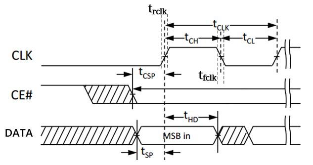
Electrical Specifications
| Parameter[1] | Description | Min. | Typ. | Max. | Unit |
|---|---|---|---|---|---|
| fsck | Bit (baud) rate | 47.96 | 48 | MHz | |
| tclk | SCK clock period | 20.83 | 20.85 | ns | |
| trclk | SCK clock rise time (10% -90%), 9pF Loading | 1.45 | ns | ||
| tfclk | SCK clock fall time (90% - 10%), 9pF Loading | 1.40 | ns | ||
| tch | SCK clock high time | 8.97 | ns | ||
| tcl | SCK clock low time | 9.01 | ns | ||
| tcsp | CS Setup delay time to active clock edge | 10.4[2] | ns | ||
| 20.8[3] | ns | ||||
| tsp | Data Setup time to active clock edge | 10.4 | ns | ||
| 20.8 | ns | ||||
| thd | Data Hold time from active clock edge | 8.97 | ns |
[1]All values are measured under 48 MHz baud rate in Clock Mode 3.
[2]Default tcsp in XIP Mode and can be adjusted by either software or hardware.
[3]Default tcsp in Register Mode and can be adjusted by either software or hardware.