
Functional Description
UART functional block diagram is illustrated in 图 33.

UART (RS232) Serial Protocol
Because the serial communication between the UART and a selected device is asynchronous, additional bits (Start and Stop) are added to the serial data to indicate the beginning and end. Utilizing these bits allows two devices to be synchronized. This structure of serial data — accompanied by Start and Stop bits—is referred to as a character, as shown in 图 34.
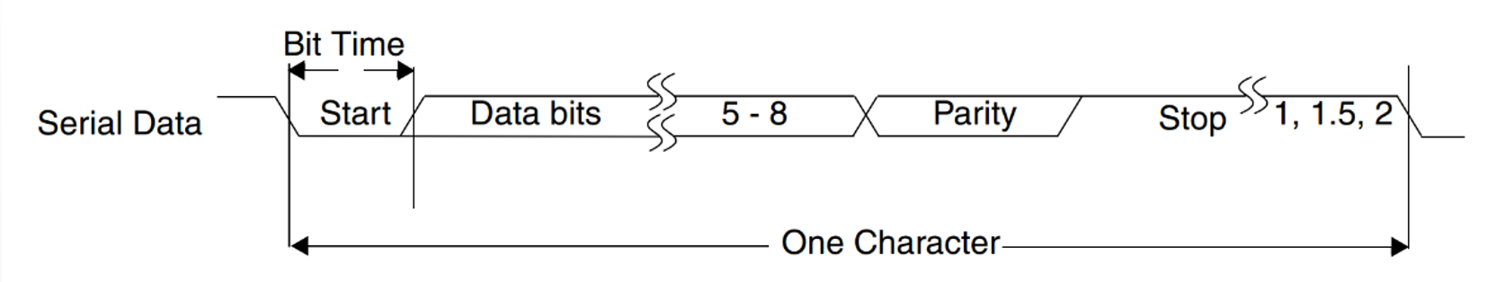
An additional Parity bit can be added to the serial character. This bit appears after the last Data bit and before the Stop bit(s) in the character structure in order to provide the UART with the ability to perform simple error checking on the received data.
The UART Line Control Register (LINE_CTRL register) is used to control the serial character characteristics. The individual bits of the data word are sent after the Start bit, starting with the least significant bit (LSB). These are followed by the optional parity bit, followed by the Stop bit(s), which can be 1, 1.5, or 2.
All the bits in the transmission are transmitted for exactly the same time duration except when 1.5 stop bits are used. This duration is referred to as a Bit Period or Bit Time; one Bit Time equals sixteen baud clocks.
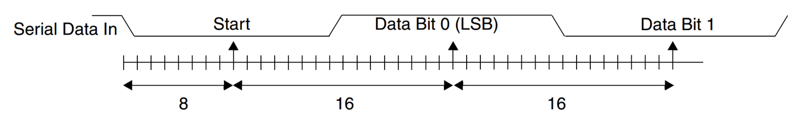
To ensure stability on the line, the receiver samples the serial input data at approximately the midpoint of the Bit Time when the start bit has been detected. The exact number of baud clocks is known for which each bit was transmitted, so calculating the midpoint for sampling is not difficult; every sixteen baud clocks sample from the Start bit to the midpoint.
Together with serial input debouncing, this sampling helps to avoid the detection of false start bits. Short glitches are filtered out by debouncing, and no transition is detected on the line. If a glitch is wide enough to avoid filtering by debouncing, a falling edge is detected. However, a start bit is detected only if the line is again sampled low after half a bit time has elapsed.
图 35 shows the sampling points of the first two bits in a serial character.
As part of the 16550 standard, an optional baud clock reference output signal (baudout_n) provides timing information to receive devices that require it. The baud rate of the UART is controlled by the serial clock—SCLK or PCLK in a single clock implementation—and the Divisor Latch register (DIV_LATCH_HIGH and DIV_LATCH_LOW).
Serial data baud rate can be calculated as follows: baud rate = (system clock frequency) / (16 * divisor). Divisor is composed of integer part (DIV_LATCH_HIGH/DIV_LATCH_LOW register) and fractional part (4-bit DIV_LATCH_FRACTION register).
Interrupts
Assertion of the UART interrupt output signal (INTR)—a positive-level interrupt—occurs whenever one of the several prioritized interrupt types are enabled and active. When an interrupt occurs, the master accesses the INT_ID register.
The following interrupt types can be enabled with the INT_EN register:
- Receiver Error
- Receiver Data Available
- Character Timeout (in FIFO mode only)
- Transmitter Holding Register Empty at/below the threshold (in Programmable TX_HDG_EMPTY interrupt mode)
- Modem Status
- Busy Detect Indication
These interrupt types are explained in detail in 表 128 .
| Interrupt ID | Interrupt Set and Reset Functions | ||||||
|---|---|---|---|---|---|---|---|
| Bit 3 | Bit 2 | Bit 1 | Bit 0 | Priority Level | Interrupt Type | Interrupt Source | Interrupt Reset Control |
| 0 | 0 | 0 | 1 | – | None | None | – |
| 0 | 1 | 1 | 0 | Highest | Receiver line status | Overrun/parity/ framing errors, break interrupt, or address received interrupt | For overrun/parity/framing/break interrupt reset control, the behavior is as follows:
|
| 0 | 1 | 0 | 0 | Second | Received data available | Receiver data available (non- FIFO mode or FIFOs disabled) or RX FIFO trigger level reached (FIFO mode and FIFOs enabled) | Reading the receiver buffer register (non-FIFO mode or FIFOs disabled) or the FIFO add above the trigger level (FIFO mode and FIFOs enabled) |
| 1 | 1 | 0 | 0 | Second | Character timeout indication | No characters in or out of the RX FIFO during the last 4 character times and there is at least 1 character in RX FIFO during this time | Reading the receiver buffer register |
| 0 | 0 | 1 | 0 | Third | Transmit holding register empty | Transmitter holding register empty (Prog. TX_HDG_EMPTY Mode disabled) or TX FIFO at or below threshold (Prog. TX_HDG_EMPTY Mode enabled) | Reading the INT_ID register (if source of interrupt); or, writing into TX_HDG (FIFOs or TX_HDG_EMPTY Mode not selected or disabled) or TX FIFO below threshold (FIFOs and TX_HDG_EMPTY Mode selected and enabled). |
| 0 | 0 | 0 | 0 | Fourth | Modem status | Clear to send or data set ready or ring indicator or data carrier detect. Note that if auto flow control mode is enabled, a change in CTS (DCTS set) does not cause an interrupt. | Reading the Modem status register |
Programmable TX Holding Empty Interrupt
The UART can be configured for a Programmable TX_HDG_EMPTY Interrupt mode in order to increase system performance; if FIFOs are not implemented, then this mode cannot be selected.
- When Programmable TX_HDG_EMPTY Interrupt mode is not selected, none of the logic is implemented and the mode cannot be enabled, reducing the overall gate counts.
- When Programmable TX_HDG_EMPTY Interrupt mode is selected, it can be enabled using the Interrupt Enable Register (INT_EN[7]).
When FIFOs and TX_HDG_EMPTY mode are implemented and enabled, the TX_HDG_EMPTY Interrupts and dma_tx_req_n are active at, and below, a programmed transmitter FIFO empty threshold level, as opposed to empty, as shown in the flowchart in 图 36.
The threshold level is programmed into FIFO_CTRL[5:4]. Available empty thresholds are: empty, 2, ¼, ½. Selection of the best threshold value depends on the system's ability to start a new transmission sequence in a timely manner. However, one of these thresholds should be optimal for increasing system performance by preventing the transmitter FIFO from running empty. For threshold setting details, refer to "FIFO_CTRL".
In addition to the interrupt change, the Line Status Register (LINE_STAT[5]) also switches from indicating that the transmitter FIFO is empty to the FIFO being full. This allows software to fill the FIFO for each transmit sequence by polling LINE_STAT[5] before writing another character. The flow then allows the transmitter FIFO to be filled whenever an interrupt occurs and there is data to transmit, rather than waiting until the FIFO is completely empty. Waiting until the FIFO is empty causes a reduction in performance whenever the system is too busy to respond immediately. Further system efficiency is achieved when this mode is enabled in combination with Auto Flow Control.
Even if everything else is selected and enabled, if the FIFOs are disabled using the FIFO_CTRL[0] bit, the Programmable TX_HDG_EMPTY Interrupt mode is also disabled. When not selected or disabled, TX_HDG_EMPTY interrupts and the LINE_STAT[5] bit function normally, signifying an empty TX_HDG or FIFO. 图 37 illustrates the flowchart of TX_HDG_EMPTY interrupt generation when not in programmable TX_HDG_EMPTY interrupt mode.
Auto Flow Control
The UART have a 16750-compatible Auto RTS and Auto CTS serial data flow control mode; if FIFOs are not implemented, this mode cannot be selected. When Auto Flow Control is not selected, none of the corresponding logic is implemented and the mode cannot be enabled, reducing overall gate counts. When Auto Flow Control mode is selected, it can be enabled with the Modem Control Register.

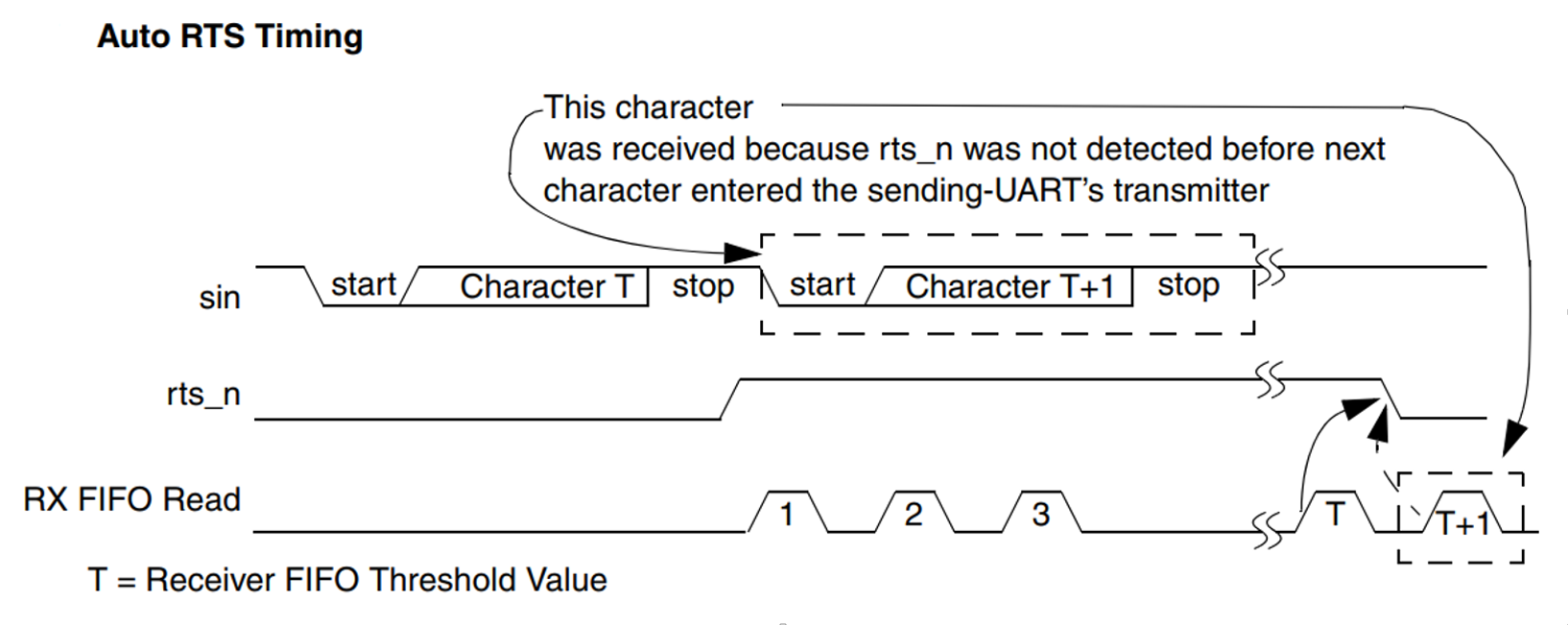
When Auto RTS is enabled, the rts_n output is forced inactive (high) when the receiver FIFO level reaches the threshold. When rts_n is connected to the cts_n input of another UART device, the other UART stops sending serial data until the receiver FIFO has available space; that is, until it is completely empty. The selectable threshold values of Receiver FIFO are:
- 1
- 1/4
- 1/2
- 2 less than full
Since one additional character can be transmitted to the UART, after rts_n has become inactive due to data already having entered the transmitter block in the other UART—setting the threshold to "2 less than full" allows maximum use of the FIFO with a safety zone of one character. Once the receiver FIFO becomes completely empty by reading the Receiver Buffer Register, rts_n again becomes active (low), signaling the other UART to continue sending data.
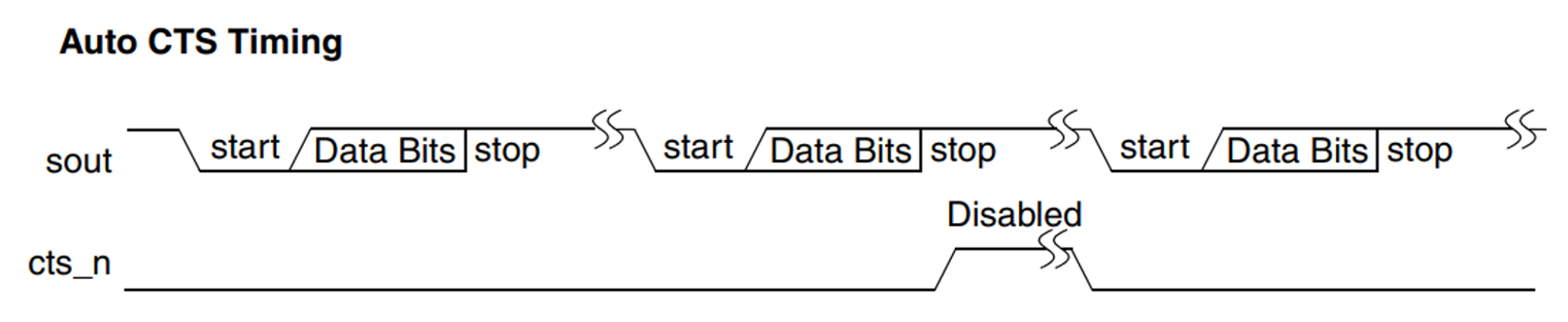
When Auto CTS is enabled (active), the UART transmitter becomes disabled whenever the cts_n input becomes inactive (high); this prevents overflowing the FIFO of the receiving UART. If the cts_n input is not inactivated before the middle of the last stop bit, another character is transmitted before the transmitter is disabled. While the transmitter is disabled, the transmitter FIFO can still be written to, and even overflowed.
FIFO and DMA
The UART module provide TWO 128-byte FIFO, one (UART TX FIFO) for transmit and one (UART RX FIFO) for receive. By configuring the Shadow RX Trigger Register (SHADOW_RX_TRG), you can program the trigger level in the RX FIFO at which the Received Data Available interrupt is generated. By configuring the Shadow TX Trigger Register (SHADOW_TX_TRG), you can program the trigger level in the TX FIFO at which the Empty Threshold Reached Interrupt is generated. The UART module supported TWO DMA channel, one for UART transmit, and one for UART receive.
